The animation feature of POV-Ray can be used to make it a spectral render engine. The basic idea is to render a set of grayscale images
- each representing a specific wavelength - and finally combine them using the CIE color match function.
To simplify this task I have created a few POV-Ray SDL scripts and examples. You'll find the download link below.
This is (as of 17th November 2015) version 0.22 of the spectral render system.
added the missing macro M_Diamond_LemonYellow within spectral_minerals.inc and bumped up the version to 0.22.
finally fixed a bug within spectral_metals.inc and changed version number to 0.21.
Update from 15th December 2013: a missing texture file added.
Update from 1st December 2013: version 0.2 of the spectral render system released.
A few bug-fixes, some more example scenes and the file spectral_materials.inc is split into different include files (spectral_glasses.inc, spectral_minerals.inc and spectral_metals.inc)
to make them easier readable and extendable. The example file diffraction.pov has changed to refraction.pov - as this is all it does while diffraction is still on my todo list.
I also would like to thank Richard Conley, who courtesy provided one of his own gem cuts.
Most importand, POV-Ray version 3.7 needs to be installed. Older versions will not work as support for the OpenEXR file format is needed.
Download the ZIP file that contains the spectral render files and some example scenes.
If you have already LightsysIV installed this is all you need. Otherwise hop over to Jaime, download and install it.
The Lightsys folder needs to be within your POV-Ray include path. There are only two files from Lightsys needed: CIE.inc and
espd_lightsys.inc. As an alternative you can download this ZIP file and copy its content
(the two files from Lightsys) into the "Spectral Render" folder.
Spectral Render Rig
Examples
Additional Files
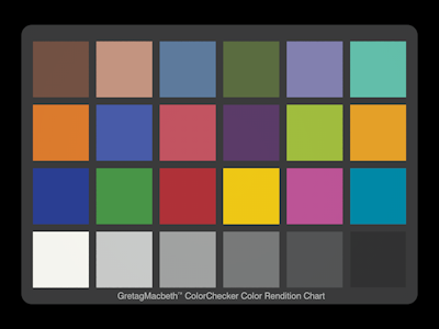
Create the image above of the GretagMacbeth(tm) ColorChecker Chart. To do so render the file ColorChecker.pov as an animation. It is meant to be rendered with a 4:3 aspect ratio so the full command line should look e.g. like this:
+W800 +H600 +A0.1 +AM2 +R3 +FE +KI1 +KF36 +KFI38 +KFF73
While the actual image dimension and anti-aliasing setting is your choice the OpenEXR output and animation setting
has to be exactly like this.
Once the full animation sequence has finished (it renders very quickly) you should have 36 OpenEXR files on disk named
ColorChecker38.exr to ColorChecker73.exr.
Now you're almost ready to run the file SpectralComposer.pov but first you need to edit it and make sure FName
matches the previously rendered sequence but without the dot and file-extension. In this case this would be:
#declare FName = "ColorChecker"
In fact, as all of the example scenes are already defined there, all you need to do is uncomment this line and comment the others. Now render SpectralComposer.pov with the same image dimension settings as ColorChecker.pov - but not as animation! Usually no antialiasing is needed for composing, so in our example the simple command line:
+W800 +H600 +FN
will create the final PNG image.
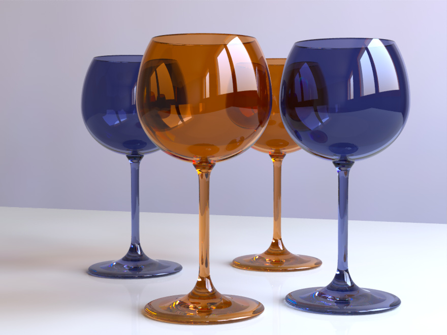
While the result might seem not that spectacular it is a proof of concept that spectral rendering is working and the
colored patches of the chart are also a good reference as those colors are already defined within
"spectral_materials.inc" as spectral data.
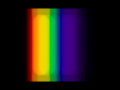
A Phillips Mastercolor 3K lamp seen through an Amici Prism
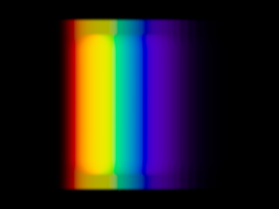
A Mitsubishi Daylight fluorescent lamp seen through an Amici Prism
The above images are rendered by the example file Prism.pov and show a scene where the camera is looking directly through
an Amici Prism at an emitting lamp.
An interesting side note: when you compose the files rendered by Prism.pov as an OpenEXR file (to preserve out-of-gamut values)
and examine the rainbow colors (e.g. within the Histogram window of IC) you'll notice that they have all negative rgb color components.
In fact they are pure spectral colors and lie exactly on the boundary of the "horseshoe" within the CIE xyz diagram. As such they are far outside
of the sRGB (or AdobeRGB for that matter) gamut.
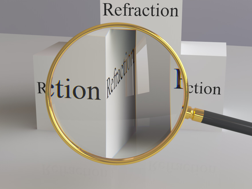
Chromatic aberration becomes stronger at the edge of the lens
This image was rendered by Refraction.pov and shows chromatic aberration produced by a magnifying glass with a lens made of N-BK7 optical glass. There are 4 commonly used optical glasses, 3 flint glasses and 3 crown glasses - all based on Schott (a German glass manufacturer) datasheets - defined for spectral rendering.
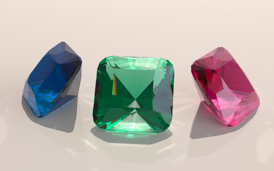
Sapphire, Emerald and Ruby
The file spectral_minerals.inc contains spectral data for amethyst, sapphire, emerald, ruby, topaz and three different diamonds. This example image was rendered by Gems.pov
and uses a gem cut created by Richard Conley and the definition for this gem (including the possibility to create various angles for pavilion and crown) is also included in the
package.
To cite Richard: "Crown main angles usually range from 20 to 40 degrees. Pavilion main angles range from 40 to 45 degrees. Generally speaking lower crown angles mean
higher brilliance and higher crown angles mean higher dispersion. Increase the pavilion main angle if the gem windows."
I'm pretty sure that I have not choosen good angles here, so there is much room for your own experiments!
Your scene description file should always include the following lines:
#version 3.7;
global_settings { assumed_gamma 1 }
#include "spectral.inc"
To run the spectral calculation it is important to use exactly the following animation command line:
+FE +KI1 +KF36 +KFI38 +KFF73
This will create a set of 36 OpenEXR images representing the wavelengths from 380 to 730 nm in steps of 10 nm.
For scene development and a quick preview you can render a single image (by not using the animation command line) and the spectral render system will switch to pre-calculated rgb values and not the spectral data. You can also specify the preview of just one specific wavelength by adding e.g.
#declare SpectralWavelength = 550;
before you include "spectral.inc". This example will create one grayscale image for the wavelength of 550nm.
As it is spectral rendering, the usual color definitions like rgb <0.75, 0.2, 0.1> cannot be used. Instead the include file "spectral_materials.inc"
defines some colors as spectral data, allows to modify and mix them and includes also ready made texture and material definitions for matte surfaces,
glass and metals.
But you can use all the colors from the ColorChecker chart directly. They are indexed from A-F for the columns and 1-4 for the rows.
For example D_CC_D3 is yellow and D_CC_A4 is white.
As this is not enough you can "mix" two colors together by using the macro "D_Average". E.g.
D_Average(D_CC_D3, 2, D_CC_A4, 1)
will combine yellow and white in a 2:1 ratio.
As an alternative there is also the macro "D_RGB". It works similar to the usual "rgb" keyword but will produce different (but quite
natural looking) results as it is based on the patches D_CC_A3 - D_CC_C3 as basis for the red, blue and green components.
You might have noticed that all declares for diffuse reflectance data are prefixed "D_" so they are more easy to identify. There are
also corresponding macros prefixed "C_" to be used where POV-Ray expects color definitions.
Some Examples:
pigment { C_Spectral(D_CC_D3) }
pigment { C_Average(D_CC_D3, 2, D_CC_A4, 1) }
pigment { C_RGB(0.7, 0.2, 0.1) }
A simple sphere with a matte texture definition would e.g. look like this:
sphere {0, 1
T_Spectral_Matte( D_RGB(0.7, 0.2, 0.1) )
}
If you prefer a more shiny surface you'll have to keep in mind that reflectivity is also wavelength dependent and therefor a "spectral" IOR definition is required. Nonetheless, defining a shiny surface with a reflectivity of 20% by using the predefined generic IOR value of 1.5 is as simple as this:
sphere {0, 1
M_Spectral_Shiny( D_RGB(0.7, 0.2, 0.1), IOR_15, 0.20 )
}
All kinds of dielectrics like glass, fluids, gemstones etc. can be defined by using the M_Spectral_Filter macro. Pure water would be:
M_Spectral_Filter( Value_1, IOR_Water, 100 )
A simple clear glass:
M_Spectral_Filter( D_CC_A4, IOR_FlintGlass_F2, 1 )
Note that the last parameter is the fade_distance and it should be used to define how transparent the material appears. But it is a bit tricky to use
as it also depends an the scale you do use for your scene.
As already mentioned simple rgb color definitions cannot be used therefor the file "spectral_lights" contains a few "real world" spectral data samples but also blackbody and CIE D illuminants. A simple light source definition using CIE D65 (overcast sky at noon) could be:
light_source { <100, 100, -50>
SpectralEmission(E_D65) * 1.5
}
A HDR sky sphere (as used by the file "world.inc") can be defined like this:
#declare Sky = sphere { 0, 1
texture {
pigment {
gradient y
scale 2
translate -y
color_map {
[0.5 SpectralEmission(E_D50)*0.3]
[1.0 SpectralEmission(E_D93)]
}
}
finish {emission 10 ambient 0 diffuse 0}
}
scale 10000
}
It is not possible to use an image_map as pigment but you can use an image_map as pigment_pattern. An example:
pigment {
pigment_pattern {image_map {png "my_image" interpolate 2} }
pigment_map {
[0.0 C_Spectral(D_CC_D2)]
[1.0 C_Spectral(D_CC_C3)]
}
}
Something more complex (e.g. as part of a layered texture) - where the diffuse reflectance data of the yellow patch is "misused" as filter for the white patch - might look like this:
pigment {
pigment_pattern {image_map {png "my_image" interpolate 2} }
pigment_map {
[0.0 C_Spectral(D_CC_A2)]
[0.5 C_RGB(0.5, 0.4, 0.1)]
[1.0 C_Spectral_Filter(D_CC_A4, D_CC_D3)]
}
}
Maps for normals or height_fields can be used without problems.
Values for transmit and filter can also be specified in a wavelength dependent way. There are a lot of possibilities to explore and I for myself have not
yet done much in this direction.
It should be possible to create the effect of diffraction grating (as seen e.g. by iridescent reflections on a compact disc) by using spectral rendering but I
have not tried it yet.
While I'm convinced that the calculations for spectral diffuse reflection and refraction are accurate there are some things that do require
further investigation. You might have noticed that I did never use the specular or phong keywords. Well, thats because a) I'm lazy but more
important b) quite unsure how to handle it within spectral rendering.
And again while I'm pretty sure that the color calculation based on the complex number for metal and alloy IOR's is correct the other values used within the material definitions are just
simplified settings as montecarlo raytracing would be needed to model the reflectance of metals in a more realistic way.
The Spectral Render System as offered for download on this page is provided under the Creative Commons CC0 1.0 Universal License.
Creative Commons - CC0 1.0 Universal
There is no requirement to give credit but it would of course be appreciated.
If you have critisism, suggestions, questions or just want to share a nice image done with spectral rendering feel free to contact me.
My e-mail address can be found at the lilysoft.org main page and I'm also regularly lurking at the POV-Ray newsgroups.
- Ive, November 2013